Duplicate the square, placing it adjacent and to the right of the first.

Delete the previous diagonals from that square.
If you do not have a copy of the SimItemBlock.dwg file, then it is straight-forward to make one.
The following instructions are for AutoCAD 2006.
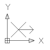
Important: The correct orientation of the SimItemBlock is essential – ensure that the orientation of the graphical elements is as shown in this diagram.
| Important: the correct orientation of the SimItemBlock is essential – ensure that the orientation of the graphical elements is as shown in this diagram. |
|
| Draw a square of scale close to that of the drawing’s conveyor width. Duplicate the square, placing it adjacent and to the right of the first. |
|
| Using End Point snaps, add diagonal lines to both squares. |
|
| Using Mid Point snaps, add half-diagonal lines to the right square. Delete the previous diagonals from that square. |
|
| Using Mid Points, add the arrow head. Add the arrow shaft. Delete the half-diagonals. |
|
| Delete the squares. |
|
The graphical elements of the SimItemBlock are complete.
The SimItemBlock is ready to be created.